 13 minutes read
This article is about using the NextThing C.H.I.P. minicomputer with Machinekit. It explains how one can write GPIO drivers for Machinekit. Furthermore, it also shows how one can build Machinekit on the CHIP and how to cross compile an RT-PREEMPT kernel for the CHIP using the CHIP-SDK.
If you are more interested in installing Machinekit and a pre-compiled RT kernel on the CHIP please take a look at "Getting started with Machinekit on the CHIP"
UPDATE September 17 2016: Applying the RT-PREEMPT kernel patch.
UPDATE September 19 2016: Copying .dtb files.
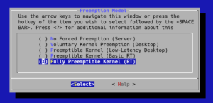
UPDATE September 22 2016: Added menuconfig screenshot
UPDATE October 2 2016: Fix missing information about wifi driver compile errors
Creating a HAL driver
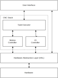
To control real world objects with Machinekit, we need a so-called "driver" to interface with the world. A driver is basically a computer program, or in our case a HAL component, that controls a particular device. Particularly interesting for Machinekit are GPIO drivers for different platforms. On a desktop computer, this could, for example, be a parallel port interface. For single board computers, this usually means interfacing with a GPIO peripheral in order toggle pins exposed via pin header. Inside the Machinekit source tree, these drivers can be in src/hal/drivers.
A HAL GPIO driver exposes the GPIO pins of the target hardware as HAL pins. Pin directions and which pins should be used by the driver is usually specified at the time of loading the HAL component. When we want to add a new GPIO driver to Machinekit we have to consider following steps:
- Finding out how to control the GPIO pins of the target platform.
- Writing the HAL component.
- Integrating the HAL component in the Machinekit build process.
Let's elaborate on these steps for the C.H.I.P.:
Controlling the C.H.I.P. GPIO pins
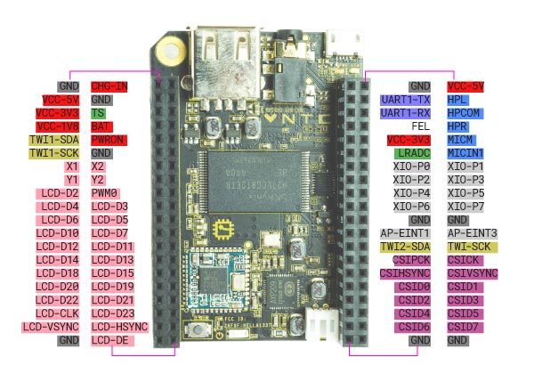
Taking a look the CHIP pinout graphic we can see that there are two types of GPIO pins exposed on the pin header. The 8 normal GPIO pins labeled XIO-Pn are located in the middle of the right pin header, when looking at the CHIP with USB connector positioned upwards. These pins can be controlled using a Linux file system driver. The relevant files are contained in the /sys/class/gpio directory. There is an official Python library for controlling these pins. However, since the file system driver GPIO pins are rather slow, we are more interested in the second type of GPIO available on the CHIP.
The second type of GPIO pins exposed on the CHIP are the CSIDn pins. Some users from the community found out how to control theses pins using mmap. Controlling the peripheral over shared memory also used in the GPIO driver for the BeagleBone Black. The original libsoc included with the sunxi-tools contains wrappers for controlling the pins over mmap. User yevgeniy-logachev additionally added an example how to use the libsoc functions to the repository. Let's take a look the functions exposed by the libsoc_mmap_gpio module.
// initialize the module
libsoc_mmap_gpio_init();
// request a pin handle
mmap_gpio *gpio_output = libsoc_mmap_gpio_request('E', 4);
// set the pin direction
libsoc_mmap_gpio_set_direction(gpio_output, OUTPUT);
// get the pin direction
mmap_gpio_direction libsoc_mmap_gpio_get_direction(mmap_gpio* gpio);
// set the pin level
libsoc_mmap_gpio_set_level(gpio_output, HIGH);
// get the pin level
mmap_gpio_level libsoc_mmap_gpio_get_level(mmap_gpio* gpio);
// free a pin handle
libsoc_mmap_gpio_free(gpio_output);
// cleanup the module
libsoc_mmap_gpio_shutdown();
These functions are straightforward to use with the exception of the libsoc_mmap_gpio_request function. In order to access a specific pin we need to know its address. I found a table of the pin address in the CHIP forum:
CSID0   132
CSID1   133
CSID2   134
CSID3   135
CSID4   136
CSID5   137
CSID6   138
CSID7   139
So far so good. But the libsoc_mmap_gpio_request function requires two arguments. A port and a pin number. Luckily user infrapro explained how to understand this: "Pin 132 is equivalent for port PE4, so we use 2nd and 3+rd letters to port access". It turned out that port and pin numbers are actually easy to calculate:
PORT = NUMBER / 32
PIN = NUMBER % 32
Using this information we have everything ready to implement the HAL component.
CHIP GPIO HAL component
For implementing the HAL GPIO driver I used the hal_bb_gpio driver as a reference. This time, we directly use the HAL C API in the component. This means that we are responsible for creating and deleting the HAL component and pins ourself. For this purpose, it is required to implement two functions in our component. int rtapi_app_main(void) is responsible for creating the HAL component. void rtapi_app_exit(void) is responsible for cleaning up everything we created. It is important that we free any memory we may have allocated in this function.
Note that I will not post the complete source here, but rather explain the most important parts of the code. I recommend you taking a look at the complete source code in the Machinekit repository.
So let's dive into the code:
In the beginning of the C file, we have to include the RTAPI and HAL header files, as well as the header file of the libsoc mmap library.
#include "rtapi.h"
#include "rtapi_app.h"
#include "hal.h"

#include "chip/libsoc_mmap_gpio.h"
I skip explaining the other included header files, which are common C headers and proceed with the platform checks and HAL module macros.
#if !defined(BUILD_SYS_USER_DSO)
#error "This driver is for usermode threads only"
#endif
#if !defined(TARGET_PLATFORM_CHIP)
#error "This driver is for the BeagleBone platform only"
#endif

#define MODNAME "hal_chip_gpio"

MODULE_AUTHOR("Alexander Roessler");
MODULE_DESCRIPTION("Driver for C.H.I.P. GPIO pins");
MODULE_LICENSE("GPL");
First of all, we check that this component is only built for usermode threads. The second check verifies that the correct build platform is enabled. Then we define the module name used throughout the HAL component. The MODULE_AUTHOR and MODULE_DESCRIPTION macros are pretty self-explaining. MODULE_LICENSE needs to be GPL if the HAL component is compiled into a kernel module.
Since creation and deletion of HAL pins have to be handled in HAL component, HAL components using the C API usually use a structure for storing pointers to all our HAL pins. For the CHIP GPIO driver this structure looks as follows:
#define HEADERS          1
#define PINS_PER_HEADER  8

typedef struct {
    hal_bit_t* input_pins[PINS_PER_HEADER * HEADERS]; // array of pointers to bivts
    hal_bit_t* output_pins[PINS_PER_HEADER * HEADERS]; // array of pointers to bits
    hal_bit_t  *input_inv[PINS_PER_HEADER * HEADERS];
    hal_bit_t  *output_inv[PINS_PER_HEADER * HEADERS];
} port_data_t;

static port_data_t *port_data;
static const char *modname = MODNAME;
static mmap_gpio * pins[PINS_PER_HEADER * HEADERS];
As can be seen, the arrays are designed either storing the maximum amount of output or input pins, since the pins are configured at runtime. The last line of the code fragment creates an array for storing the GPIO pin handles for the libsoc mmap module.
Now let's take a look at the macros which are used for HAL component parameter passing:
static char *input_pins;
RTAPI_MP_STRING(input_pins, "input pins, comma separated.  P0-P7 use 0-7");

static char *output_pins;
RTAPI_MP_STRING(output_pins, "output pins, comma separated.  P0-P7 use 0-7");
The code means that the parameters are passed as a string which can be accessed with the variables input_pins and output_pins. As stated in the comments, the pins have to be passed as comma separated list, e.g. 0,3,4.
This leads us to the initialization code of the HAL component in rtapi_app_main. First of all the HAL component is created:
// init driver
comp_id = hal_init(modname);
if(comp_id < 0) {
    rtapi_print_msg(RTAPI_MSG_ERR, "%s: ERROR: hal_init() failed\n", modname);
    return -1;
}
Then memory is allocated for the structure to store our HAL pin handles:
// allocate port memory
port_data = hal_malloc(num_ports * sizeof(port_data_t));
if(port_data == 0) {
    rtapi_print_msg(RTAPI_MSG_ERR, "%s: ERROR: hal_malloc() failed\n", modname);
    hal_exit(comp_id);
    return -1;
}
Note that num_ports is always 1 for the CHIP driver.
Next, the control module is initialized by calling the configure_control_module function. Since the libsoc module handles the mmap call we only need to call the correct function. In the BeagleBone Black driver, the mmap function is called instead.
static void configure_control_module() {
    int ret;

    ret = libsoc_mmap_gpio_init();
    if (ret != 0)
    {
        rtapi_print_msg(RTAPI_MSG_ERR, "%s: ERROR: Unable to map Control Module: %s", modname, strerror(errno));
        exit(1);
    }
}
Finally, it is time to create the HAL pins. Since the creation of the output pins works completely similar I only add the code fragment for adding the input pins.
    // configure input pins
    if(input_pins != NULL) {
        data = input_pins;
        while((token = strtok(data, ",")) != NULL) {
            int pin = strtol(token, NULL, 10);
            mmap_gpio *gpio_pin;

            if((pin < 0) || (pin > 7)) {
                rtapi_print_msg(RTAPI_MSG_ERR, "%s: ERROR: invalid pin number '%d'. Valid pins are 0-7 for P0-P7.\n", modname, pin);
                hal_exit(comp_id);
                return -1;
            }

            data = NULL; // after the first call, subsequent calls to strtok need to be on NULL

            // Add HAL pin
            retval = hal_pin_bit_newf(HAL_OUT, &(port_data->input_pins[pin]), comp_id, "chip_gpio.in-%02d", pin);

            if(retval < 0) {
                rtapi_print_msg(RTAPI_MSG_ERR, "%s: ERROR: pin %02d could not export pin, err: %d\n", modname, pin, retval);
                hal_exit(comp_id);
                return -1;
            }

            // Add HAL pin
            retval = hal_pin_bit_newf(HAL_IN, &(port_data->input_inv[pin]), comp_id, "chip_gpio.in-%02d.invert", pin);

            if(retval < 0) {
                rtapi_print_msg(RTAPI_MSG_ERR, "%s: ERROR: pin %02d could not export pin, err: %d\n", modname, pin, retval);
                hal_exit(comp_id);
                return -1;
            }

            // Initialize HAL pin
            *(port_data->input_inv[pin]) = 0;

            // Initialize GPIO pin
            gpio_pin = get_gpio(pin);
            if (gpio_pin == NULL)
            {
                rtapi_print("%s: ERROR: failed to open GPIO pin %d", modname, pin);
                hal_exit(comp_id);
                return -1;
            }
            pins[pin] = gpio_pin;

            retval = libsoc_mmap_gpio_set_direction(gpio_pin, INPUT);
            if (retval == DIRECTION_ERROR)
            {
                rtapi_print("%s: ERROR: failed to set GPIO direction %d", modname, pin);
                hal_exit(comp_id);
                return -1;
            }
            rtapi_print("pin %d setup with mode input\n", pin);
        }
    }
Walking trough the code we can see that we first split the string by using strtok. Then we create two HAL pins (one for the pin value and the other for the invert pin) by calling hal_pin_bit_newf. After that, we make sure that the input pins are initialized with a default value. The actual libsoc calls are issued to get a pin handle and to set the pin direction.
The final step for initializing the HAL component is to register the HAL functions. In the case of a GPIO driver, there are usually two functions. One for reading the GPIO pins read and one for writing the GPIO pins write. It is good practice to use two separate functions for this operations so we can read the GPIO pins at the beginning of our thread cycle and update the output pins at the end of the cycle.
// export functions
rtapi_snprintf(name, sizeof(name), "chip_gpio.write");
retval = hal_export_funct(name, write_port, port_data, 0, 0, comp_id);
if(retval < 0) {
    rtapi_print_msg(RTAPI_MSG_ERR, "%s: ERROR: port %d write funct export failed\n", modname, n);
    hal_exit(comp_id);
    return -1;
}

rtapi_snprintf(name, sizeof(name), "chip_gpio.read");
retval = hal_export_funct(name, read_port, port_data, 0, 0, comp_id);
if(retval < 0) {
    rtapi_print_msg(RTAPI_MSG_ERR, "%s: ERROR: port %d read funct export failed\n", modname, n);
    hal_exit(comp_id);
    return -1;
}
The HAL component cleanup function rtapi_app_exit is very simple. We just free our pins handles and release the memory map:
void rtapi_app_exit(void)
{
    int i;

    hal_exit(comp_id);

    for(i=0; i<HEADERS*PINS_PER_HEADER; i++) {
        libsoc_mmap_gpio_free(pins[i]);
    }
    libsoc_mmap_gpio_shutdown();
}
This leaves us with the two remaining functions for writing and reading the GPIO pin states into the HAL component. Again, they are very similar so I will only explain the write_port function.
static void write_port(void *arg, long period)
{
    int i;
    port_data_t *port = (port_data_t *)arg;

    // set output states
    for(i=0; i<HEADERS*PINS_PER_HEADER; i++) {
        int retval;

        if (port->output_pins[i] == NULL) {
            continue; // short circuit if hal hasn't malloc'd a bit at this location
        }

        mmap_gpio *pin = pins[i];

        if((*port->output_pins[i] ^ *(port->output_inv[i])) == 0) {
            retval = libsoc_mmap_gpio_set_level(pin, LOW);
        }
        else {
            retval = libsoc_mmap_gpio_set_level(pin, HIGH);
        }
        if (retval == LEVEL_ERROR) {
            rtapi_print("%s: ERROR: failed to set GPIO pin %d", modname, i);
            return;
        }
    }
}
Passed to the function as an argument is the port data structure port. Note that we have explicitly defined this behavior when registering the HAL functions. Using a for loop, we iterate over all pins in the structure. This makes it necessary to check for the pin beeing already created with comparing the pointer to NULL. Remember, that not necessarily all pins are output pins.
Next, we take the GPIO pin handle in order to use the libsoc functions. Then we set the GPIO pin level using the libsoc_mmap_gpio_set_level function. The output pin and invert pin of the HAL component are XORed, in order to get the expected behavior.
The read_port function is very similar. However, instead of setting the pin level, we read the pin level from the GPIO port and apply it to the HAL input pins. (Remember that physical input pins are HAL_OUT pins).
Adding the GPIO driver to the Machinekit project
The last step of creating the HAL GPIO driver involves adding the HAL component to the Machinekit build process. Since the driver component is platform dependent, it is good practice to only build it if the correct target platform is specified, in our case --with-platform-chip.
In order to achieve this, I had to edit the following files:
* src/Makefile
* src/Makefile.inc.in
* src/configure.ac
Long story short, I basically used the TARGET_PLATFORM_ZEDBOARD as reference. If you are interested in what exactly I had to modify please take a look at the pull request.
Using the CHIP with Machinekit
After having a HAL GPIO driver ready for the CHIP, it is time to prepare the CHIP for running Machinekit with RT PREEMPT kernel.
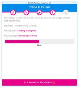
Flashing the CHIP
First of all, we need to flash the CHIP with a fresh Debian Linux image. The easiest way to achieve this is to use the CHIP online flasher, which can be executed from the Chrome or Chromium browser. There is not a lot say about this step since it just worked!
Building Machinekit on the CHIP
The next step involves building Machinekit from source on the CHIP. This is necessary since the CHIP GPIO driver has not been merged into upstream Machinekit yet. Once the patch has been merged and made its way into the ARM Debian packages, you can safely skip this step. However, it may still be useful for you as a reference if you want to port Machinekit to a new platform.
EDIT: The patch is merged into upstream Machinekit. You can now install the Machinekit via apt-get install machinekit machinekit-dev machinekit-rt-preempt after adding the Machinekit repository.
Add the Machinekit repository
First, we need to add the Debian package repository containing the Machinekit packages:
sudo apt-key adv --keyserver hkp://keyserver.ubuntu.com:80 --recv 43DDF224
sudo sh -c \
  "echo 'deb http://deb.machinekit.io/debian jessie main' > \
  /etc/apt/sources.list.d/machinekit.list"
sudo apt-get update
Compile Machinekit
The steps from the Machinekit documentation work perfectly fine.
# remove Machinekit pacakges if already installed
sudo apt-get remove --purge machinekit
# install dependencies
sudo apt-get install libczmq-dev python-zmq libjansson-dev pkg-config \
  libwebsockets-dev libxenomai-dev python-pyftpdlib cython bwidget lsb-release python-avahi
# install the build packages
sudo apt-get install git dpkg-dev
sudo apt-get install --no-install-recommends devscripts equivs
mkdir repos
cd repos
git clone https://github.com/machinekoder/machinekit
cd machinekit
git checkout origin/chip-io
debian/configure -pr
sudo mk-build-deps -ir
# build and configure Machinekit
cd src
./autogen.sh
./configure --with-platform-chip --with-rt-preempt
make
sudo make setuid
During the Machinekit configure step, I hit a problem at the step of looking for the Boost::Python module. Basically, the error message was not very helpful, since it did not describe the correct problem. Taking a look in the build.log finally gave me a useful hint: virtual memory exhausted: Cannot allocate memory. Turned out that the CHIP ran out of virtual memory during the test build.
First I tried to specify the virtual memory using the following commands:
ulimit -a
ulimit -m 60000
ulimit -v 60000
However, this did not fix the configure problems. Chengxi pointed out that this problem can be fixed by mounting a USB drive as swap partition. So I connected a 8GB flash drive (make sure there is no data on the flash drive) to the CHIP and issued the following commands:
sudo mkswap /dev/sda1
sudo swapon /dev/sda1
Voila! Now running make the build worked perfectly fine. (Just took some time...)
Don't forget to register Machinekit in the .bashrc:
sh -c "echo 'if [ -f ~/repos/machinekit/scripts/rip-environment ]; then\n\
    source ~/repos/machinekit/scripts/rip-environment\n\
    echo \"Environment set up for running Machinekit\"\n\
fi\n' >> ~/.bashrc"
Build a RT PREEMPT kernel for CHIP
Last but not least, it is time to compile a kernel with RT PREEMPT patch for the CHIP. Compiling the CHIP kernel turned out to be surprisingly easy since NextThing provides a pre-configured Vagrant configuration for cross compiling to the CHIP target.
First one needs to download and install the CHIP SDK on the computer (not on the CHIP).
git clone https://github.com/NextThingCo/CHIP-SDK.git
cd CHIP-SDK
vagrant up
Once the SDK is up and running we can login:
vagrant ssh
For compiling the Linux kernel for the CHIP-SDK I used this wiki entry as a reference.
First of all, one needs to install the build dependencies and the cross compiling toolchain:
# install build dependencies
apt-get install git build-essential fakeroot kernel-package zlib1g-dev libncurses5-dev lzop
# install cross compiling toolchain
apt-get install gcc-arm-linux-gnueabihf binutils-arm-linux-gnueabihf
Next one needs to check out the Linux kernel source from NextThingCo:
cd
git clone https://github.com/NextThingCo/CHIP-linux.git
cd CHIP-linux
Check out the git branch containing the kernel version matching the kernel installed on your CHIP. In my case this was debian/4.4.11-ntc-1:
git checkout -b debian/4.4.11-ntc-1 origin/debian/4.4.11-ntc-1
Copy the kernel configuration from the CHIP to the CHIP SDK. In order to do that, I enabled the shared folder in the CHIP-SDK Vagrant configuration .Vagrantfile. On my host Linux computer I used scp to copy the config file over.
cd <path to CHIP-SDK>
scp chip@chip.local:/boot/config-4.4.11 .
Copy this file to your kernel build tree CHIP-linux.
Now you need to patch the Linux kernel with the PREEMPT_RT patch. The patch can be found at kernel.org. I used the 4.4.12 patch since there is no patch exactly matching the 4.4.11 kernel.
wget https://www.kernel.org/pub/linux/kernel/projects/rt/4.4/older/patch-4.4.12-rt20.patch.gz
cat patch-4.4.12-rt20.patch.gz | patch -p1
Next you need to run menuconfig:
make ARCH=arm CROSS_COMPILE=/usr/bin/arm-linux-gnueabihf- menuconfig
In the kernel configuration enable the following settings
CONFIG_PREEMPT_RT_FULL: Kernel Features > Preemption Model > Fully Preemptible Kernel (RT)- Enable
HIGH_RES_TIMERS: General Setup > Timers subsystem > High Resolution Timer Support (already enabled) - add a local version suffix: General setup > Local version - append to kernel release, I used
rtas suffix
Now it is time to compile the kernel:
make ARCH=arm CROSS_COMPILE=/usr/bin/arm-linux-gnueabihf- -j 2
After compiling one needs to install the kernel modules to /tmp/lib:
mkdir -p /tmp/lib
make ARCH=arm CROSS_COMPILE=/usr/bin/arm-linux-gnueabihf- INSTALL_MOD_PATH=/tmp/lib modules_install
Additionally, you need to compile the RT8723BS module since it is an out-of-tree module:
# clone the repository
cd
git clone https://github.com/NextThingCo/RTL8723BS.git
# apply the debian patches
cd RTL8723BS
git checkout -b debian origin/debian
for i in debian/patches/0*; do  echo $i; patch -p 1 <$i ; done
# remove the no-error=date-time compiler flag
sed '/EXTRA_CFLAGS += -Wno-error=date-time/d' -i Makefile
# remove the no-error=incompatible-pointer-types compiler flag
sed '/EXTRA_CFLAGS += Wno-error=incompatible-pointer-types/d' -i Makefile
# compile the module
make -j 2 CONFIG_PLATFORM_ARM_SUNxI=y ARCH=arm CROSS_COMPILE=/usr/bin/arm-linux-gnueabihf- -C /home/vagrant/CHIP-linux/ M=$PWD CONFIG_RTL8723BS=m  INSTALL_MOD_PATH=/tmp/lib
make -j 2 CONFIG_PLATFORM_ARM_SUNxI=y ARCH=arm CROSS_COMPILE=/usr/bin/arm-linux-gnueabihf- -C ~/CHIP-linux/ M=$PWD CONFIG_RTL8723BS=m  INSTALL_MOD_PATH=/tmp/lib modules_install
Now the Linux kernel is ready to be deployed to the CHIP. I used the approach of replacing the existing kernel on the CHIP. Note that this might lead to an unbootable CHIP if there is an error in the kernel configuration or build. For details on how to manually boot a specific kernel please refer to this wiki.
The following lines need to be executed on the CHIP SDK VM. Note that I have mounted the root folder of the SDK on my host machine to ~/CHIP-SDK on the guest machine. This can be done be enabling the shared folder in the .Vagrantfile of the SDK.
mkdir -p ~/CHIP-SDK/deploy
cd ~/CHIP-linux/
cp arch/arm/boot/zImage ../CHIP-SDK/deploy/vmlinuz-4.4.11-rt20+
cp .config ../CHIP-SDK/deploy/config-4.4.11-rt20+
cp System.map ../CHIP-SDK/deploy/System.map-4.4.11-rt20+
cp arch/arm/boot/dts/*.dtb ../CHIP-SDK/deploy/linux-image-4.4.11-rt20+/
cd /tmp/lib/lib/modules
cp -r 4.4.11-rt20+/ ~/CHIP-SDK/deploy/
# compress the kernel
cd ~/CHIP-SDK
tar -czvf 4.4.11-rt20.tar.gz deploy/
This leaves us with a complete Linux kernel for the CHIP in the deploy folder of the CHIP-SDK. I used scp to copy the files to the CHIP:
# copy the kernel to the CHIP
scp 4.4.11-rt20.tar.gz chip@chip.local:/tmp/
# connect to the CHIP
ssh chip@chip.local
cd /tmp/
tar xvz 4.4.11-rt20.tar.gz
cd deploy
sudo cp -r 4.4.11-rt20+/ /lib/modules/
cp -r -v linux-image-4.4.11-rt20+ /usr/lib/
mkdir -p /boot/dtbs/4.4.11-rt20/
cp -v linux-image-4.4.11-rt20+/sun5i-r8-chip.dtb /boot/dtbs/4.4.11-rt20/sun5i-r8-chip.dtb
sudo cp System.map-4.4.11-rt20+ config-4.4.11-rt20+ vmlinuz-4.4.11-rt20+ /boot/
cd /boot/
# overwrite Linux image
sudo cp vmlinuz-4.4.11-rt20+ zImage
# reboot the CHIP
sudo reboot
After a reboot, you should have a RT PREEMPT kernel running on the CHIP.
$uname -a
Linux chip 4.4.11rt+ #1 SMP PREEMPT Wed Aug 31 13:45:03 UTC 2016 GNU/Linux
Short usage example
To test the newly created CHIP GPIO driver one can use the following short example, which can be found in configs/ARM/CHIP/ in the Machinekit repository.
from machinekit import hal
from machinekit import rtapi as rt

# we need a thread to execute the component functions
rt.newthread('main-thread', 1000000, fp=True)

# load GPIO driver
rt.loadrt('hal_chip_gpio', output_pins='0,1,2,3', input_pins='4,5,6,7')
gpio = hal.Component('chip_gpio')
gpio.pin('out-00').link('square')

# load siggen
rt.loadrt('siggen')
siggen = hal.Component('siggen.0')
siggen.pin('frequency').set(10.0)
siggen.pin('clock').link('square')

# setup update functions
hal.addf('chip_gpio.read', 'main-thread')
hal.addf('siggen.0.update', 'main-thread')
hal.addf('chip_gpio.write', 'main-thread')

# ready to start the threads
hal.start_threads()
This example HAL configurations initializes the hal_chip_gpio HAL component with 4 input and 4 output pins. Furthermore, the siggen component is used to output a square waveform with 10Hz on one of the pins. Using a jumper wire we can use this configuration to prove that both, input and output pins, work with our driver.
Wrapping up
In this blog post, we discussed how to add a new GPIO driver to Machinekit, using the NextThing CHIP as an example. Furthermore, it is explained how one can compile a RT PREEMPT kernel for the platform. The result is a CHIP with working RT PREEMPT kernel and GPIO driver for Machinekit. Moreover, a short example code is presented to test the GPIO driver. The complete code can be found in the pull request on GitHub. In further blog posts, I will explore how to use the ported CHIP to control some real world objects.
I hope you enjoyed reading this blog post and I appreciate your comments and feedback.
Your Machine Koder